In this release I was able to make significant progress, though there were things along the way that I wasn’t expecting, and they took so much time to resolve. The main thing was to be able to load geometry from file, not hardcoding it, and then be able to apply some kind of coloring for the visualisation purposes. Also, I’ve re-used my Flexible Vertex Buffers which allows flexibility when it comes to managing Vertex Buffers. Another major planned thing was Input Handling, so at the very least I would be able to rotate my camera aound the scen using mouse. The two major unplanned things were implementing Resource Handles and the rework of the camera system. The first one was easy, but significantly improve code readibility and type safety. The latter though… that’s like the other story 🙂 Spoiler alert, eventually with this rework I was able to achieve a nice result.
Features
Load Geometry from File
This was the biggest thing I wanted to implement this release. This feature would give me the “biggest bang for the buck”. There were many libraries to consider, however, I’ve decided to go with my own solution. Some time ago I’ve decided that I wanted to learn more about lodaing game assets from hard drive, things like geometry or images. I’ve even went as far as implementing my own PNG decoder, which took me a while, but was an amazing journey and very, very rewarding. This library is not very good, there were some decisions I’ve made which I didn’t know back then were not great, but it works and for whatever reason, I really enjoyed doing things from scratch.
The library is rather easy to use, basically you create your own Asset Manager and then you point a file you want to load and the decoder you want to use, which is optional, the decoder can be picked automatically based on file extension. Then, the library will load a file from disc to local memory and decode if necessary. The decoding results in having a common representation of given asset. In other words, no matter if you load PNG or BMP file, once loaded, they will have the same format. Once that is done, you get the access to the raw memory and you can do whatever you want with the asset, like uploading it to the GPU.
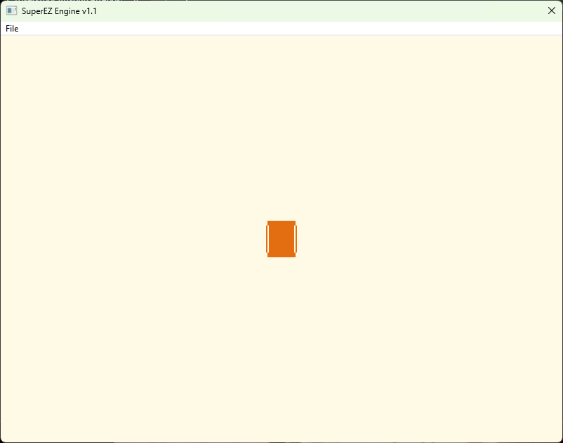
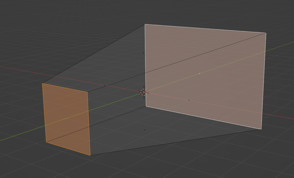
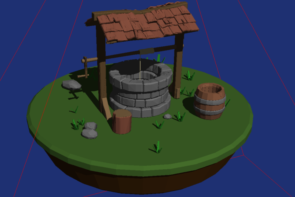
In this release I’ve only used the geometry part to load the Wavefront files. There are some requirements though, like speciffic axis setup, triangulation is required and the separate objects needs to be grouped together, but that’s easy to handle.
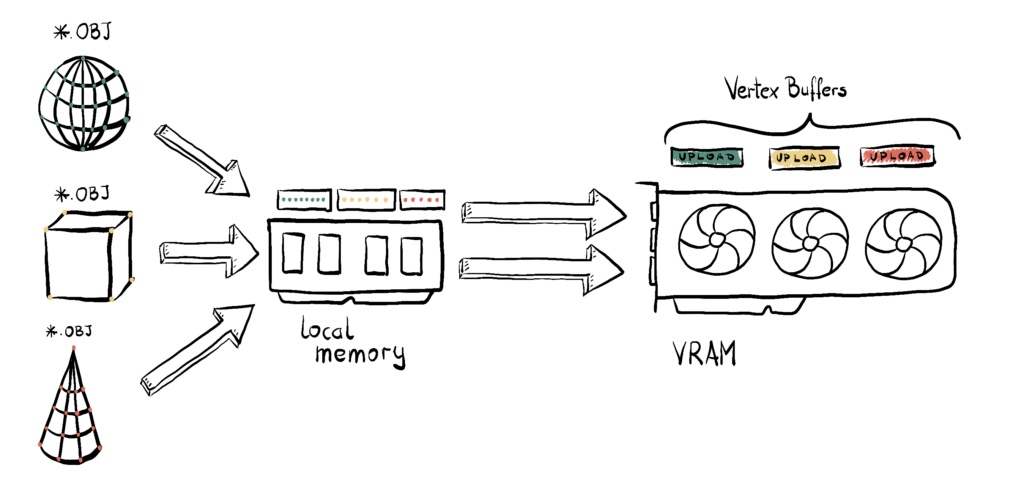
So the flow is, first I load the whole Wavefront file to the memory. This file contains separate objects as group. For each such object, I create vertex buffer that contains the position and also I generate some semi-random coloring, just so that we can see some nice things on the screen. During the Vertex Buffer creation, I immediatley uplad it to the GPU using the Upload Heap. Note that this is not the way commercial engines work, usually uploading resources to the GPU is a complex system that can support things like decompression or streaming them on demand. Moreover, using Upload Buffers in such way can lead to performance issues. However, this is very easy to use and understand, that at this point this is the most important thing for this implementation.
Once we have that, I create the abstract Mesh object, which creates Vertex Buffer Views necessary for binding and cointains indices to the Vertex Buffers. This introduces a kind of abstraction layer, but is also really easy to use and understand.
Flexible Vertex Buffers
Once my geometry is loaded into local memory, the next step is to upload it to the GPU. Now, this idea had been simmering in the back of my mind for a while: what’s the best way to do this?
Most tutorials online show a single struct that defines a vertex—something like position, normal, texture coordinates, etc.—and then a vertex buffer is just an array of these structures. Simple. Clean. But…
As I built previous engines and the complexity grew, two big pain points started to emerge:
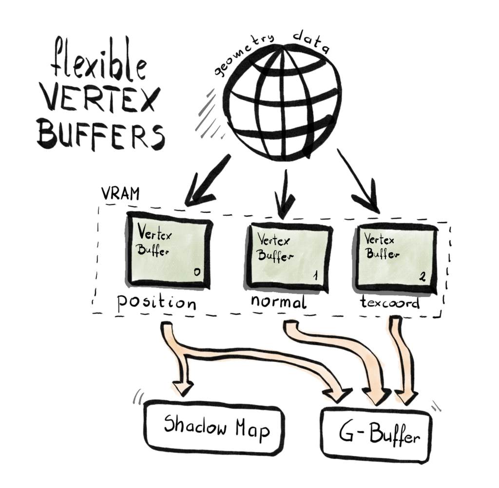
- Not all render passes need the full vertex layout. For example, a G-Buffer pass might need position, normal, tangent, UVs, and more—but a Shadow Map pass only needs position. So a one-size-fits-all vertex layout becomes wasteful and restrictive.
- Vertex layout bloating over time. Every new feature—like normal mapping, per-vertex AO, skinning, or instance IDs—adds more elements to the vertex struct. Even if a pass doesn’t need them, they’re still there, taking up space and bandwidth.
These two issues led me to rethink the design and build what I now call the Flexible Vertex Buffer (FVB) system. (Yeah, I’m a little proud of the name.)
Here’s the general idea – instead of having one big Vertex Buffer, where each vertex contains all the elements required by all the Render Passes, you create separate Vertex Buffer for each element – one for position, one for color, one for texture coordinate, and so on. Then, each Render Pass will pick and choose which element it needs and bid corresponding buffer to the rendering pipeline.
Since each pass might use a different set of vertex elements, I needed a flexible way to build input layouts on demand. Enter variadic templates:
class InputLayout
{
public:
	InputLayout();
	~InputLayout();
	template <typename T, typename... Types>
	void AppendElementT(T firstArg, Types... restArgs)
	{
		AppendElement(firstArg);
		AppendElementT(restArgs...);
	}
	template<typename T>
	void AppendElementT(T firstArg)
	{
		AppendElement(firstArg);
	}
	D3D12_INPUT_LAYOUT_DESC GetInputLayoutDesc();
private:
	void AppendElement(VertexStream vertexStream);
	std::vector<D3D12_INPUT_ELEMENT_DESC> inputElementsList;
};
Each render pass can now configure its input layout like this:
void TestPass::ConfigurePipelineState()
{
	// Pre-AutomaticPrepare Procedure
	inputLayout = renderContext.CreateInputLayout();
	renderContext.GetInputLayout(inputLayout)->AppendElementT(
        VertexStream::Position, VertexStream::Color);
}
During rendering, the appropriate vertex buffers are bound based on what the shader expects:
void RenderContext::BindGeometry(HCommandList commandList, HMesh mesh)
{
	commandLists[commandList.Index()]->GetCommandList()->
        IASetPrimitiveTopology(D3D_PRIMITIVE_TOPOLOGY_TRIANGLELIST);
	D3D12_VERTEX_BUFFER_VIEW vbvPosition[] =
	{
		meshes[mesh.Index()]->GetPositionVertexBufferView(),
		meshes[mesh.Index()]->GetColorVertexBufferView()
	};
	commandLists[commandList.Index()]->GetCommandList()->
        IASetVertexBuffers(0, 2, vbvPosition);
}
Right now, all render passes (okay, there’s one) use the full set of data, so we only bind everything. But the plan is to support pass-specific binding combinations soon.
At this point you might think – do I need to somewhat change my shaders to accomodate for this solution? Well, here’s the beauty of it: the shader code doesn’t change. You still define your inputs like this:
struct PSInput
{
float4 position : SV_POSITION;
float4 color : COLOR;
};
PSInput VSMain(float4 position : POSITION, float4 color : COLOR)
//PSInput VSMain(float4 position : POSITION)
{
PSInput result;
result.position = mul(position, viewProjection);
result.color = color;
return result;
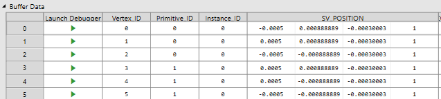
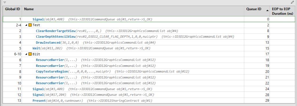
}This is what you might expect out of the PIX capture.
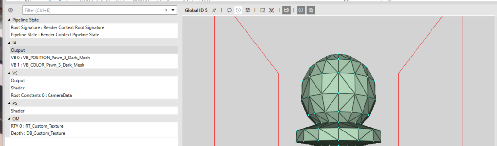
And that it is, I think for the purposes of this engine, it gives us lots of felxibility, it improves the code and capture readibility.
Note on Performance
This architecture is known as a non-interleaved layout—also called a “structure of arrays” (SoA) approach. While it offers a lot of flexibility and modularity, especially when different render passes require different vertex data, there may be a performance tradeoff.
GPUs are optimized for interleaved vertex buffers (“array of structures”), where all attributes for a single vertex are stored contiguously. That layout helps with memory caching and reduces over-fetch. In contrast, when using separate buffers for each attribute, the GPU might perform more memory fetches, possibly leading to cache misses or memory bandwidth waste—especially on mobile or bandwidth-constrained hardware.
Modern game engines implement a hybrid approach, some parts that are quite common are interleaved, while other less common parts are non-interleaved. I’ll be profiling this setup to measure actual impact. If it turns out to be a problem, we might implement a hybrid approach later on. But for now, the clarity and extensibility of FVB feels like the right move.
Resource Handles
Some time ago, I settled on the nature of my RenderContext. I decided to split the system into two general levels of abstraction: low-level and high-level.
The low-level side is basically a thin wrapper around DirectX 12 — things like ID3D12Resource, vertex buffers, heaps, etc. This part is pretty raw and is exposed directly to the graphics API.
The high-level side is more generic and abstract. It includes things like RenderTarget, Mesh, and Texture. These are mostly API-agnostic, and they allow for more architectural and design-driven thinking. When you work on rendering at a high level, you want to say: “Create a RenderPass, attach a RenderTarget, set up a Pipeline State”, not “Allocate heap memory and manually set up a resource descriptor.”
I’ve grown to really like this design. It feels clean and separates concerns well. But there was a big challenge that emerged as the engine evolved: how do you reference low-level things from high-level structures?
The Naive Start
At first, I kept it simple — too simple. I stored my low-level resources in std::vectors, and used raw indices to refer to them.
std::vector<VertexBuffer*> vertexBuffers;

auto index = vertexBuffers.size();
vertexBuffers.push_back(new VertexBuffer(...));
Then in my high-level structures, I’d store that index — just a size_t, or even worse, a uint32_t. And to be fair… it worked. For a while.
The good part: I avoided raw pointers to DX12 resources in high-level objects, keeping responsibilities clean.
The bad part: the code quickly became unreadable, error-prone, and frankly ugly. I was passing unsigned integers all over the place. It wasn’t clear what any of them meant. Was 5 a texture index? A vertex buffer? A pipeline state? Who knew? More importantly, the compiler didn’t care. I had completely lost type safety.
Enter: Resource Handles
So, I stopped overthinking and implemented a simple, generic handle system. Here’s the full code:
template<typename T>
class Handle {
public:
    using IndexType = size_t;

    Handle() : m_index(InvalidIndex()) {}
    explicit Handle(IndexType index) : m_index(index) {}

    bool IsValid() const { return m_index != InvalidIndex(); }
    IndexType Index() const { return m_index; }

    bool operator==(const Handle& other) const { return m_index == other.m_index; }
    bool operator!=(const Handle& other) const { return !(*this == other); }

    static constexpr IndexType InvalidIndex() { return static_cast<IndexType>(-1); }

private:
    IndexType m_index;
};

// Aliases for different resource types
using HTexture       = Handle<Texture>;
using HVertexBuffer  = Handle<VertexBuffer>;
using HRenderTarget  = Handle<RenderTarget>;
So what changed?
Yes — under the hood, it’s still just an index into a vector. But now, each handle is strongly typed. A Handle<Texture> can’t be passed where a Handle<VertexBuffer> is expected. You get both type safety and intent clarity. And it looks cleaner too:
// Create the resource and return a handle
HVertexBuffer RenderContext::CreateVertexBuffer(...) {
    size_t index = vertexBuffers.size();
    vertexBuffers.push_back(new VertexBuffer(...));
    return HVertexBuffer(index);
}

// Use the handle in high-level structures
auto vbHandle = renderContext.CreateVertexBuffer(...);
renderContext.CreateMesh(vbHandle, ...);
No more guessing what that 5 means. The type tells you it’s a vertex buffer handle — not a texture, not a pipeline state. The only thing I’m not thrilled about is the H prefix in HTexture, HVertexBuffer, etc. I really don’t like prefixes in general — they tend to clutter things. I considered going with TextureHandle, RenderTargetHandle, etc., but they felt a bit too verbose. I might revisit the naming later, or maybe wrap them in a namespace. For now, HTexture does the job, and doesn’t offend my eyes too much.
This was one of those cases where a small utility class ended up improving the architecture significantly. Type-safe, readable, and no more mystery integers flying around. The engine’s growing, and so are the lessons.
Drawing Multiple Meshes
Now, since I have all the geometry data I need in place, the next thing to do was to provide it to the Render Passes, so that they can actually perform the drawing. Since all the Mesh instances are being handled within the Render Context, the only thing to do was to provide a way for a Render Pass to provide the handle to given Mesh (which could be a single index) and we’re good to go.
// In Render Context...
HVertexBuffer CreateVertexBuffer(
    UINT numOfVertices,
    UINT numOfFloatsPerVertex,
    FLOAT* meshData,
    const CHAR* name
);
void CreateMesh(
    HVertexBuffer vbIndexPosition,
    HVertexBuffer vbIndexColor,
    const CHAR* name
);
void BindGeometry(
    HCommandList commandList,
    HMesh mesh
);
void DrawMesh(
    HCommandList commandList,
    HMesh mesh
);
UINT GetNumOfMeshes();

// ...in the Engine...
for (const auto& meshName : meshNames)
{
    auto vbIndexPositionAndColor = renderContext.CreateVertexBuffer(...);
    renderContext.CreateMesh(...);
}

// ...and then in Render Pass
for (int i = 0; i < renderContext.GetNumOfMeshes(); i++)
{
	renderContext.BindGeometry(commandList, HMesh(i));
	renderContext.DrawMesh(commandList, HMesh(i));
}
I’ve kept the interface clean and simple so far, you simply point to a mesh you want to draw, and then Render Context takes care of the rest. Now this solution will probably need to be changed in the future, because it has too many design flaws, but for now, since we only render all meshes or nothing, it should be enough.
Input Handling
Another big feature introduced in this release was Input Handling. Fortunately, I had most of the code ready from previous iterations. We only supporte one technology – the Raw Input for both keyboard and mouse support. It handles events provided by Windows via the Windows Procedure function. To future prof this code (for example to support game pads down the line), I’ve decided to use the Observer design pattern.
First, let’s have a high level overview of the design, and then we will cover the details of the implementation a little bit more. As with many Observer patterns, we have two key players – we have a Subject and and Observer (in some cases refered to as Listener). The first one will register Observers and will provide all the information to them. In our case, the Subject will be the winMessageSubject and will be plugged in the Window Procedure.
Subject<WinMessageEvent> winMessageSubject;
RawInput rawInput;
// ...
void Engine::Initialize()
{
	rawInput.Initialize();
	winMessageSubject.Subscribe(&rawInput);
    // ...
}
And then, later in the code, in the Window Procedure, we read.
LRESULT CALLBACK WindowProcedure(HWND hwnd, UINT uMsg, WPARAM wParam, LPARAM lParam)
{
	WinMessageEvent winMessageEvent(hwnd, uMsg, wParam, lParam);
	winMessageSubject.Notify(winMessageEvent);
	// ...
}
I’ve built the low-level input handling via the Windows Raw Input API to achieve more precise and efficient processing of mouse and keyboard input. The RawInput class registers both devices during initialization, ensuring we receive raw data directly from the hardware. When input events come in, the class distinguishes between mouse and keyboard data and routes each to dedicated handlers. Mouse handling tracks movement deltas, button presses/releases, and wheel scrolling using a structured flag system, while keyboard input maintains the current and previous state of each key, enabling detection of discrete key transitions (like a key being pressed this frame but not the last). After each frame, deltas and transient input states are reset to ensure clean state tracking for the next frame. This setup gives us fine-grained control over input events, which is essential for real-time applications like games or simulators. Here’s how it looks like in action.
const bool isXAxisRotation =
    rawInput.GetMouseXDelta() != 0 && rawInput.IsMiddleButtonDown();
const bool isYAxisRotation =
    rawInput.GetMouseYDelta() != 0 && rawInput.IsMiddleButtonDown();
if (isXAxisRotation || isYAxisRotation)
{
	arcballCamera->Rotate(
        0.1f * rawInput.GetMouseYDelta(),
       -0.1f * rawInput.GetMouseXDelta(), 0.0f
    );
}
In this case we’re checking if the mouse moved and if the middle mouse button were clicked at the same time. If so, we query the mose delta in both x- and y-axis, and we apply this to the camera rotation.
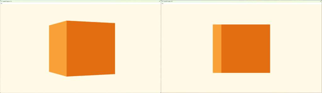
Camera System Rework
There is this piece of wisdom that I honestly believe is true to the bone: “Everyone has a plan until they get punched in the mouth” by Mike Tyson. This is so very true. I did have a plan for the release, the last thing I wanted to do was to take a look at possibility to quickly switch between Orthographic and Perspective camera. It turned out, there were some deep flaws in the overall design to the system, so it was clear that I need to rework the entire thing. Everything started when I wanted to implement a feature, where you would be allow to switch between Orthographic and Prespective Camera by click of a button. Morover, I really wanted that when the switch happens, the rotation, zoom, and things like that would match.
Previously, I had separate class for Orthographic and Perspective camera, meaning that I had to have two different objects for each type of the camera. The main point of this rework was to merge these two things into one class.
Another big design decision was to make the rotation a part of that Camera class. Previously, this was in the hand of the Camera Controler. Additionally, I did the ground work for a big change from using Euler angles for rotation in favor of the spherical cooridantes, but more on that later.
Orbit Camera
The very last thing I did was related to the Orbit Camera. I had it somewhat working, but after a little bit more testing, it turned out that it had some significant flaws and basically wasn’t working as intended. If I had to be honest, I did set up a little more broad goal, to achieve this kind of Blender-like camera, which is an orbital camera with zoom, ability to switch between orthographic and perspective camera, and easily set camera to either front, side or top by a press of a button. Some of the issues, like not aliging rotation between orthographic and perspective cameras, were solved with the Camera System Rework, the biggest issue was with the Orbit camera (which I previously called Arcball, but it wasn’t a representative name). There were many symptoms of that camera not working correctly:
- If I rotate 90 degrees right (or left), I wasn’t able to rotate up and down anymore
- If I rotate 180 degrees right (or left), I was able to rotate up and down, but in reversed order
- If I rotate 270 degrees right (or left), I wasn’t able to rotate up and down anymore as well
- If I rotate up (or down), the rotation is not continuing, but rather it flips around and suddenly goes back, even though it was supposed to go up
I did start to research this problem a little bit, and it turned out it is a pretty common pitfall in this situation, and it has to do with Euler angles – it is called Gimbal Lock.
Let’s start with explaining what Euler angles are, because this and rotation matrices are key to understand what is going on.
Euler Angles Explained
Euler angles are a way to describe a 3D orientation using three separate rotations around the principal axes: typically X (pitch), Y (yaw), and Z (roll). The rotations are applied in a specific order, and each one changes the coordinate system for the next. This method is intuitive for humans and often used in UI sliders or keyframe animation systems.
For example:
- Yaw rotates around the vertical axis (left/right),
- Pitch rotates around the lateral axis (up/down),
- Roll rotates around the longitudinal axis (twist/tilt).
However, Euler angles come with limitations—especially when trying to represent smooth and continuous rotations in 3D space. Now that we undersand this, let’s try to put a magnifying glass on all the things that were happening.
Gimbal Lock Explained
Gimbal lock occurs when two of the three rotational axes become aligned, effectively losing one degree of freedom. In practice, this means you can no longer rotate independently along all axes, and your camera starts behaving erratically.
In the context of your orbit camera:
- When the pitch approaches ±90 degrees, the yaw and roll axes begin to align.
- This causes the system to lose the ability to distinguish between certain directions, leading to the odd behavior you observed (unable to rotate, reversing controls, or snapping back).
This is a fundamental limitation of using Euler angles for 3D rotations in certain configurations. Finally, let’s take a look at the spherical solution and how it started to work eventually.
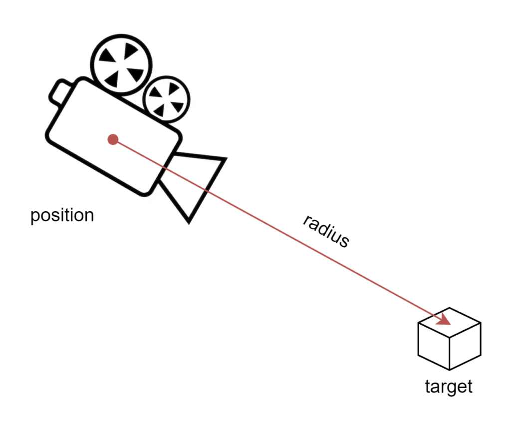
Spherical Coordinates and the Solution
To fix this, I transitioned from Euler angles to spherical coordinates. In spherical coordinates, a point in space is defined by:
- Radius
r(distance from the origin), - Azimuth
θ(angle around the vertical axis — like yaw), - Elevation
φ(angle up/down — like pitch).
This model maps naturally to orbit-style camera behavior, where:
- The target point is the origin.
- The camera moves on the surface of an imaginary sphere.
- You never run into gimbal lock because you are not composing axis rotations—you’re directly controlling angles on a sphere.
The camera’s position can be calculated as:
x = r * cos(φ) * sin(θ)
y = r * sin(φ)
z = r * cos(φ) * cos(θ)
Then, the camera simply looks at the origin. This approach gives you:
- Seamless orbiting,
- Smooth zoom (by adjusting
r), - Consistent control without weird flipping or reversal.
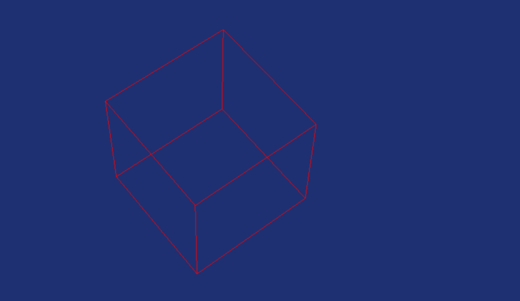
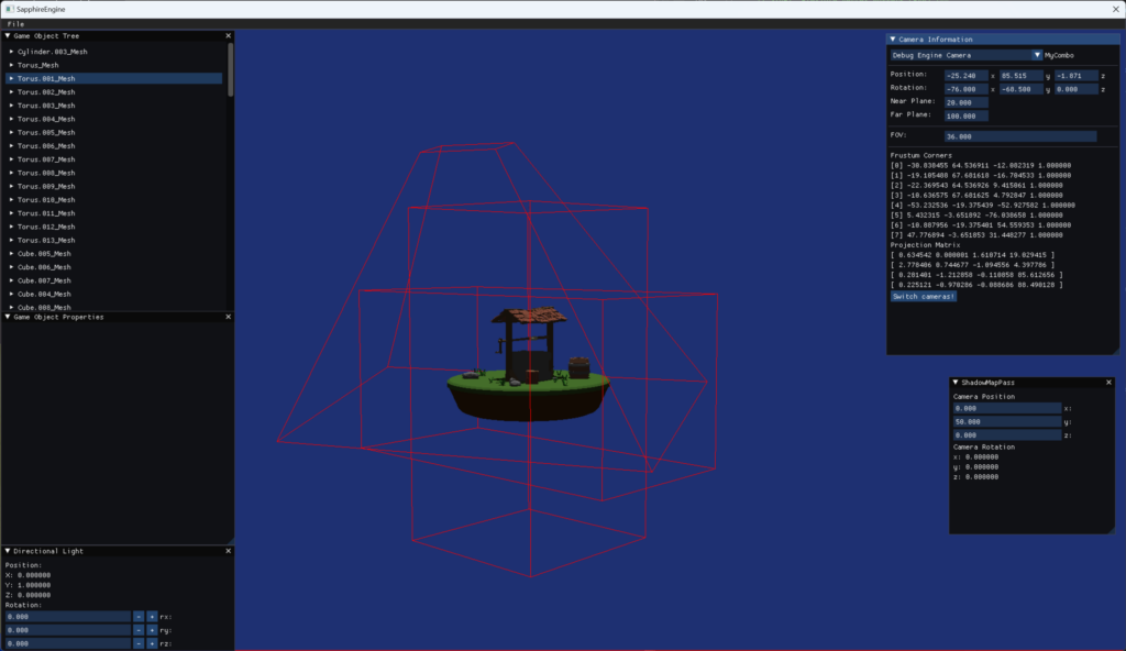
With this implementation, everything started to behave correctly. The orbit camera became predictable, intuitive, and aligned with my original vision — giving me a solid foundation for the Blender-like camera system I wanted.
Summary
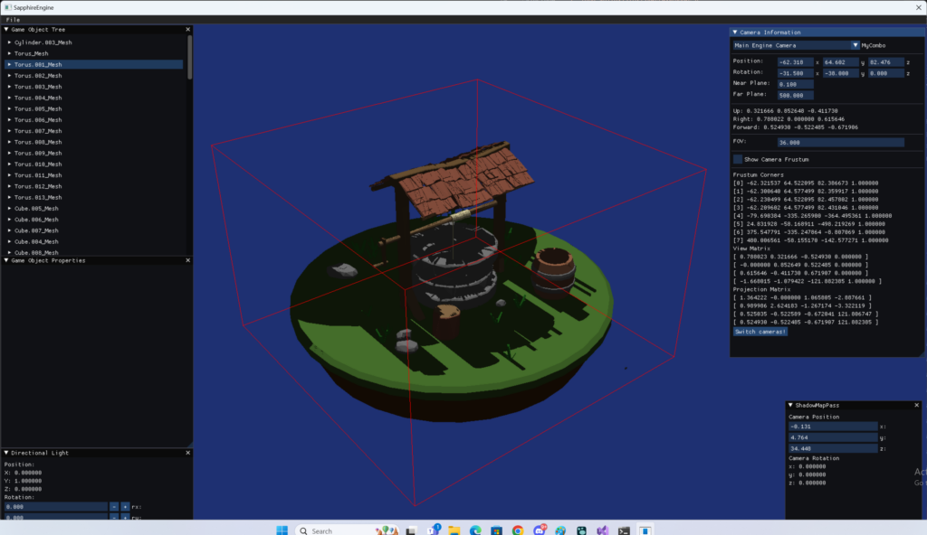
This was supposed to be an easy release, but took much more time than I initially anticipated, but I’m very happy with the result. Now the engine is much more responsive and we don’t have those annoying behaviors with camera rotations. We can load different scens, which is nice and we can inspect them much more clearly with the new orbit camera. Finally, we’ve improved the code robustess by introducing the handlers and future profed it by using the Observer pattern when it comes to Input Handling.
The next release is alrady jam packed, but among other things I’m planning to add ImGui support, simple texturing, simple scene graph and some very basic editor functionalities, so stay tuned!