I decided to start this series to give you guys some updates about what is going on with the engine and what significant feature I have been working on lately. I think this is important to see how work gets done with game engine development, so maybe others will find some inspiration and will start working on their own, which is an amazing developer’s journey.
Motivation
The main motivation for developing this feature is that, in order to develop tightly fit camera frustums for the shadows, and eventually Cascade Shadow Maps, I need to be able to visually see the frustums and how they interact with each other. Additionally, visualizing frustums and getting access to camera’s inner data would allow me to understand cameras and geometric transformations better.
Description
I want to be able to see the camera frustum within the world. I started by quickly drawing what I would like to see in Blender, just to have my eyes on the prize. Basically, I want to see the wireframe of the frustum, and I want to clearly see the near and far plane. I don’t necessarily want to see other things, like semi-transparent walls or wall selection, just the wireframe.
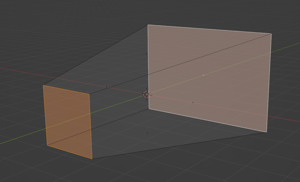
At the beginning, I also wanted this to look very good, so I decided to give Geometry Shader a try and basically try to draw those lines as quads, so they can have a proper width and potentially proper anti-aliasing.
Render Interface
One of the problems I had was that all of the cameras were scattered all over the code. You could basically create them anywhere in the code, starting from the Game project, ending on the ShadowMapPass. I also wanted to have the ability to add debug cameras, like orthographic front or side cameras.
In order to be able to shaw debug information for all othem and potentially be able to show frustums for any of them, I had to have it centralized. I decided to add a static array of Camera pointers in the RenderInterface class. This is the class which is usually available everywhere, starting from the Engine class, ending in the Renderer and each RenderPass has a pointer to it.
I decided to have a static array, meaning that its size has to be known at the compile time. The order of all of those pointers is known and described in the enum.
enum CameraNames
{
  MainCamera,
  DebugCamera,
  ShadowMapCamera,
  FrontCamera,
  CameraNamesSize
};
// ...
class RenderInterface
{
  // ...
  Camera* cameras[CameraNames::CameraNamesSize];
  bool showCameraFrustum[CameraNames::CameraNamesSize];
  // ...
}
Debug Render Pass
Now that I have easy access to all the cameras, I was ready to add a new render pass. I decided that the next step was to draw a wireframe box, but not using the standard route – I want to render it using wireframe. And for that, I needed a new Debug Render Pass. That pass would take all the cameras from Render Interface, and will draw a wireframe of its frustum in the world space (if requested by the user).
Wireframe Rendering
The first thing I wanted to do was to actually draw a cube. However, I didn’t want to go the usual route, where I create a box in Blender, and then load it from file. Instead, I created a separate class that will be reponsible for generating geometry on the spot. I would start with the box, since this is really easy, followed by maybe a frustum, and then more complex stuff, like capsules or spheres.

Geometry Shader
I though it would be a good idea to give Geometry Shaders a try, since I have never actually used them before. And given that Mesh Shaders are getting more and more attention, it would be good for me to at least be familiar with its poor predecessor. Couple of things you need to know about Geometry Shaders:
- They work on entire primitives instead of single vertex, like Vertex Shaders
- Has the ability to emit or discard vertices
- It has the ability to change primitive topologies (lines on input, triangles on output)
This sounds like a very good case for those kind of shaders, we could provide lines that represent the frustum, and then create a quad. This should allow us to define the thickness of the line and would potentially help us deal with the aliasing. There are also challenges though, we would have to make sure that those quads always face the camera and we would have to deal with joints somehow, so the line looks like a single one. Writing Geometry Shaders also sound relatively easy, at least when it comest to the easy ones.
struct GSInput
{
  float4 position : POSITION;
};

struct GSOutput
{
  float4 position : SV_POSITION;
};

[maxvertexcount(2)]
void main(line GSInput input[2], inout LineStream<GSOutput> outStream)
{
  GSOutput output;

  output.position = input[0].position;
  outStream.Append(output);
  output.position = input[1].position;
  outStream.Append(output);
}
This is a simple bypass shader, meaning this simple copies the inputs you provide. You can tell by looking at its singature – you’ve got line at the input and LineStream at the output. Then, although you can freely append and discard vertices, you have to declare the maximum number of vertices that your geometry shader will emit.
This particual shader does actually nothing, it is a simple bypass – it takes whatever pair of vertices that it on the input, and it simply appends it at the end of the line stream. To bo honest, I never really did more then this. In the end it turned out that the simple wireframe was enough for me, so more complex geometry shaders will have to wait for better times.
Frustum Corners
One of the most challenging things I had to deal with was to calculate camera frustum corners in the world space. I didn’t really know how to do it, there were several things I had to consider in the solution. It would have to work for both orthographic and perspective cameras, it would have to be in the world space. After researching this subject a little, it turns out that there are two ways to do this.
The first one is pretty straight forward, if you know the positions of the planes, you could manually calculate the frustum corners, but I couldn’t really figure this way out. The second solution looked a little bit more generic and therefore better – calculating the corners from the view-projection matrix of the camera.
When you create the camera transformation, you need to prepare two matrices – a view matrix that basically has the rotation and position encoded in it, and a projection matrix that contains either orthographic or perspective projection. You multiply those two together, and you apply this transormation to all vertices, effectively putting them in the so-called NDC space, from which you simply discard the depth and just project the x and y values to the actual pixels.
The trick to retrieve frustum corners from view-projection matrix, is to prepare a box that would represent the NDC space, and then multiply all those 8 vertices by the inverse of the view-projection matrix of the camera. There is a little caviat though, it is not entirely the same for the orthographic and perspective projection, there is a little difference – in the perspective case, once you multiply, you have to divide the result by the w-value. Here’s the code for the perspective camera.
void Sapphire::PerspectiveCamera::CalculateFrustumCorners()
{
  auto tempViewProj = view * projection;
  for (int i = 0; i < 8; i++)
  {
    frustumCorners[i] = DirectX::XMVector4Transform(
      frustumCornersNDC[i], tempViewProj.Invert());
    // The line below only applies to the perspective camera
    // You should delete it for orthographic camera
    frustumCorners[i] /= frustumCorners[i].w;
  }
}
Here’s how the frustum corners NDC look like.
const DirectX::SimpleMath::Vector4 frustumCornersNDC[8] = {
  DirectX::SimpleMath::Vector4(-1.0f, -1.0f, 0.0f, 1.0f),
  DirectX::SimpleMath::Vector4(-1.0f, 1.0f, 0.0f, 1.0f),
  DirectX::SimpleMath::Vector4(1.0f, -1.0f, 0.0f, 1.0f),
  DirectX::SimpleMath::Vector4(1.0f, 1.0f, 0.0f, 1.0f),
  DirectX::SimpleMath::Vector4(-1.0f, -1.0f, 1.0f, 1.0f),
  DirectX::SimpleMath::Vector4(-1.0f, 1.0f, 1.0f, 1.0f),
  DirectX::SimpleMath::Vector4(1.0f, -1.0f, 1.0f, 1.0f),
  DirectX::SimpleMath::Vector4(1.0f, 1.0f, 1.0f, 1.0f),
};
This is obviously for DirectX, for OpenGL it will look different, because of the different coordinate system. I also wonder if the w coordinate is really necessary, maybe I should be able to get by without it, maybe I’ll check that one day.
Depth Buffer
The last thing I had to deal with was that initially, I though that wireframe rendering can’t use the depth buffer.
Fortunately, I was wrong. It turns out that wireframe can use the depth buffer, just as any other kind of rendering. I provided the depth buffer from the Forward pass, enabled depth checking, and that was enough to get this actually working.
Summary
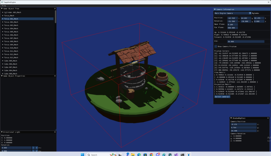
Eventually, I was able to get this whole thing working. Now I’m able to see debug information for any camera, and on top of that, I can draw frustum of any of the pre-defined cameras.
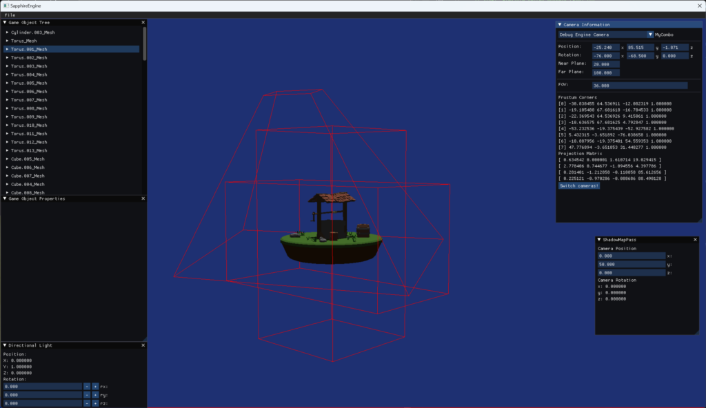
And here’s how it looks like in action.
In the end I decided not to follow through with geometry shaders, it wasn’t really needed and casual wireframe rendering was enough. I did leave though the implementation to support geometry shaders, so maybe I will pick it up in the future.
All this effort was done so that I can first better understand the geometry transformations and the concept of the camera in drendering, and two – and more inportantly – to help debug and visualise the next concept I want to work on, which is tightly fitting the light camera frustum in the Shadow Map pass to the view camera frustum.
Leave a Reply