Introduction
In this chapter we will be creating a Swap Chain – a set of structures necessary to setup frame presentation backend. It includes the set of buffers, sometimes referred to as surfaces, where our rendered frame will be stored prior to the presentation.
Along the way, we will learn about unwanted screen tearing effect and how to overcome it. We will take a quick look at how Windows operating system composes many window applications into a single desktop image. We will also add one more debug feature which would allow us to track non-released COM objects. Finally we will make sure that unwanted transition to fullscreen mode is disabled.
In the Performance Corner we will use Visual Studio tools to see how much heap memory we consume. This chapter will not bring any visual changes, but it will bring a significant progress to the engine’s backend.
Architecture
There are no architectural changes in this chapter, we will simply add a few members and methods to the existing classes.
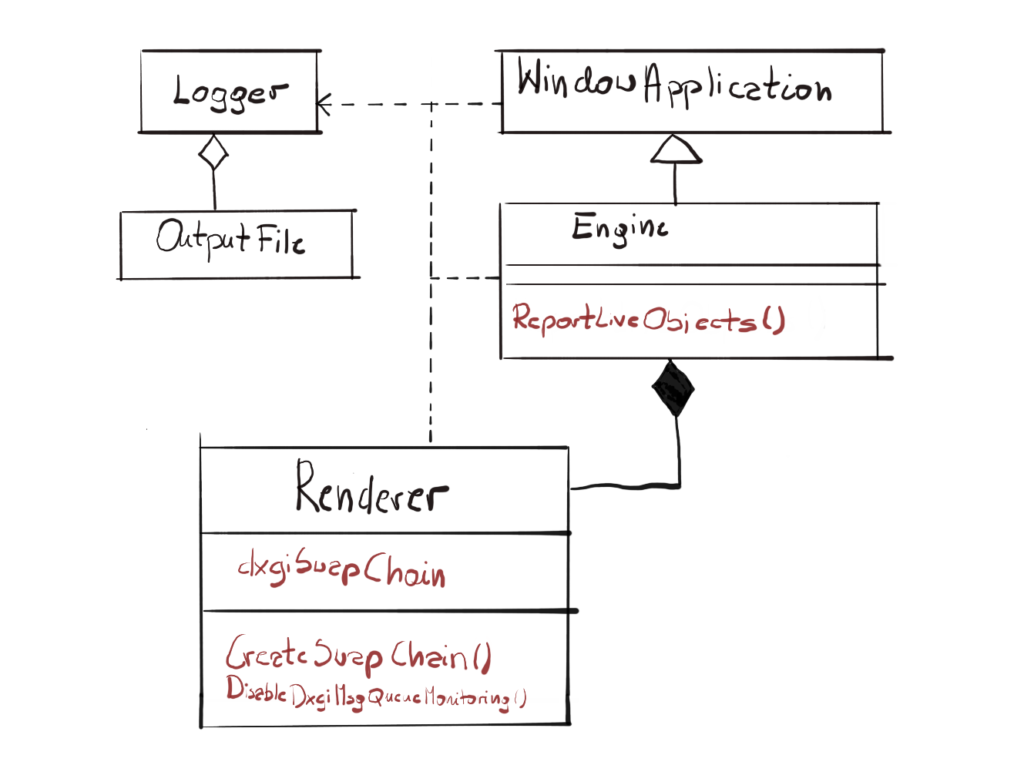
I’ve only marked the new members and methods. We will probably have to redesign this a little, extract some functionality to new classes and so on. I’m also planning to cover the Design Patterns throughout this course. We have already covered Singleton, we will cover more as soon as I can find appropriate ones and fit it in the engine.
Screen Tearing
Imagine the situation, where the frame is currently being presented on the screen. It is being read from some space in the memory and being displayed on the monitor, pixel by pixel, while at the same time GPU is writing new color values down for the new frame to the same memory from which the monitor is fetching its data. If the GPU will fill that space in memory faster than the display is reading the data, then you would end up with portion of the frame on the screen showing the current frame and the other portion showing the new frame, which most probably would be tilted a little. That effect is called screen tearing and can produce images like the one on figure 2.

One of the solutions for screen tearing problem is actually pretty simple – what if we had two separate surfaces in memory? One will be used by the monitor to read the current frame datafrom, while the other would be used by the GPU to produce the next frame. When both GPU and display are done, we can simply switch the pointer and we are ready for the next iteration.
Swap Chain
This structure is called a Swap Chain and it is an actual implementation of the solution to the screen tearing problem. The Swap Chain will create a number of buffers to store our frames produced by the GPU. One buffer, called the Front Buffer will be used for frame presentation to the screen. The other buffer, called the Back Buffer, will be used by GPU to produce next frame.
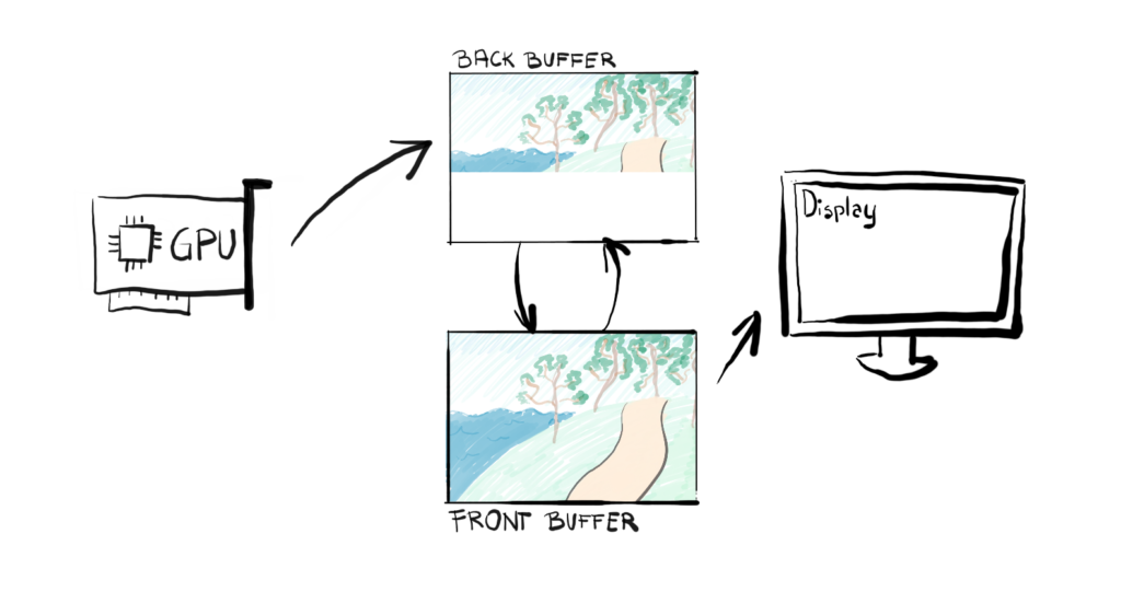
The act of switching the buffers is called the flip and from that point, up to the next flip, the Back Buffer becomes Front Buffer, and the Front Buffer becomes the back buffer. Thanks to the simplicity of this solution, the flip is actually just changing a pointer from pointing to Front Buffer, to point to Back Buffer.
We create the Swap Chain by calling the CreateSwapChainForHwnd() function. It used to be the CreateSwapChain(), but then Microsoft decided that this function should no longer be used so we will use the new one.
void Renderer::CreateSwapChain() {DXGI_SAMPLE_DESC sampleDesc; ZeroMemory(&sampleDesc, sizeof(sampleDesc)); sampleDesc.Count = 1; sampleDesc.Quality = 0;DXGI_SWAP_CHAIN_DESC1 swapChainDesc;ZeroMemory(&swapChainDesc, sizeof(swapChainDesc));swapChainDesc.Width = 0;swapChainDesc.Height = 0;swapChainDesc.Format = DXGI_FORMAT_R8G8B8A8_UNORM;swapChainDesc.BufferUsage = DXGI_USAGE_RENDER_TARGET_OUTPUT;swapChainDesc.BufferCount = FRAME_COUNT;swapChainDesc.SwapEffect = DXGI_SWAP_EFFECT_FLIP_SEQUENTIAL;swapChainDesc.SampleDesc = sampleDesc;IDXGISwapChain1* tempSwapChain;ExitIfFailed(dxgiFactory->CreateSwapChainForHwnd(commandQueue,hwnd, &swapChainDesc, nullptr, nullptr, &tempSwapChain));tempSwapChain->QueryInterface(IID_PPV_ARGS(&dxgiSwapChain));}tempSwapChain->Release();
Our function takes six arguments. First is the Command Queue that we want our Swap Chain to be associated with. We have created it previously along with our Device. Second is the Window Handle of a window that we want to bind our Swap Chain to. Note how the Swap Chain, the Window and the Command Queue depend on each other.
Next we have a Swap Chain description structure, followed by the Fullscreen description structure. Finally we have a pointer to the Output that we want to restrict our Swap Chain to. We don’t care about the fullscreen mode, nor the output, so at the moment, so we set all of them to NULL.
Last parameter will be filled with a pointer to the IDXGISwapChain1 interface. You might have noticed that we are using an address to tempSwapChain. That it because our function returns that interface. However, we need to store the IDXGISwapChain3 interface because it has the GetCurrentBackBufferIndex() function which we will need later. Since there is no casting mechanism in COM, we need to use the function QueryInterface() to obtain it. This method queries an object using the IID of the interface to which the caller wants a pointer. If the object supports that interface, this function retrieves a pointer to the interface, while also increasing the reference count.
Swap Chain Description
Let’s take a look at the DXGI_SWAP_CHAIN_DESC1 structure. First we need to provide the width and height of the surfaces that will store our frame. We could set them the same values as the window dimensions, but if we put zeros in there, those dimensions will be fetched automatically from the associated window.
Next we have to specify the format of our surfaces. We have many options available, but we’ve picked the most popular one – R8G8B8A8_UNORM. This simply means that each color component of a pixel – Red, Green, Blue and Alpha – will be stored on 8 bits. In total, each pixel will be stored on 32 bits. Often you refer to this format as 32bpp, bits-per-pixel. The UNORM part means that each value is an unsigned-normalized-integer. With 8-bits you are able uniquely identify 256 integer values. The UNORM format means that for all of those 256 integers are evenly mapped to the floats ranging from 0.0f (which maps to integer 0) to 1.0f (which maps to integer 256). In other words, there is a linear dependency between the <0.0f,1.0f> float range and <0,256> integer range. We will be using those floats to represents four color components in our 32bpp color pallet.
Next we specify two parameters related to the buffer. We will be using it as an output Render Target, so we set BufferUsage to DXGI_USAGE_RENDER_TARGET_OUTPUT. Then we need to think how many buffers we want in our Swap Chain. For the simplicity, we will settle on two – one will act as Front and the other as Back Buffer. This is a common practice in most of the game engines. We used a constant there, just in case we want to change it in the future.
At the first glimpse, you might think that it would be better to have more than two buffers. This way of thinking is generally correct, but it has its downsides. First, games are not movies – they take input from the player, possibly many players in multiplayer games. Because of that, they simply can’t render too many frames ahead, they don’t know what the player will do which will affect the objects to render. He can shoot or jump at any time. Second, yes, the presentation should be better, but in order to do that, we need to render those frames and to do that, we need data. Each frame comes with its own set of data, which is usually pretty big. Each additional buffer in the Swap Chain means more data to process, share with the GPU and synchronize.
Desktop Window Manager
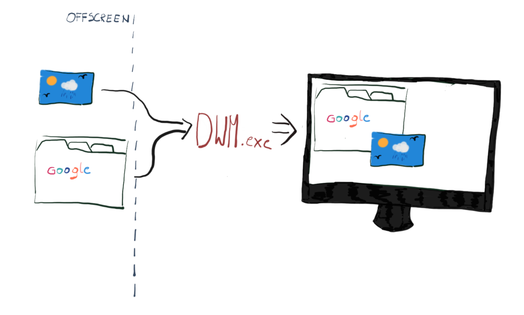
There is one additional component that takes part in frame presentation – a window composer called Desktop Window Manager, or DWM for short. DWM is responsible for presenting all of the windows that you see on the screen and it was introduced in Windows Vista. One of its main advantages is that it uses hardware acceleration, which allows it to present windows in interesting ways, like 3-D-opened window browsing or transparent windows.
DWM uses GPU and DirectX for window composition. The desktop is actually a DirectX surface, drawn as a quad that covers the entire screen. Each window program has an off-screen surface buffer in video memory that it draws its window content to, and then DWM composes each such surface into a final desktop image.
The DWM composes many windows into a single desktop image, however, it can be even more performant if you present your application in a fullscreen mode. It detects that the application’s window covers the desktop entirely and if yes, it can use one of the shortcuts to present it even faster.
So our Back Buffer has to somehow end up in the hands of the DWM. The behavior of the buffer after it is ready to be presented on the display is defined by a so-called Swap Effect.
Swap Effect
Swap Effect defines what happens to the Back Buffer after calling the Present() function. There are four options available: Discard, Sequential, Flip-Discard and Flip-Sequential. The first two use the so called blit model and the last two use so called flip model. In DirectX 12 only the flip Swap Effects are available, but we will take a look at both.
We know that DWM takes care of the composition and that the Back Buffer is actually an off-screen buffer – somehow the Back Buffer needs to end up on the DWM side.
In blit model, the entire Back Buffer (when ready to present) is being physically copied to the DWM internal surfaces. That is a very costly operation. In the flip model on the other hand, the Back Buffer surface memory is shared with DWM, so DWM has a direct access to it, which is a great performance improvement.
But the optimizations doesn’t end there. If your Back Buffer surface has the same dimensions as your desktop and your window covers the entire screen, you can bypass DWM entirely and present the frame directly from your surface, increasing performance even more. This optimization has two forms – the Direct Flip and the Independent Flip. In the Direct Flip, the window composer detects the full coverage of the screen and decides not to compose and put the content directly on the screen. In the Independent Flip, the DWM removes itself entirely, and it gives the power to present to the application itself.
When we present, we can either leave the content of the Back Buffer, or we can immediately discard it. That’s the meaning behind the Discard suffix – this is the one we will pick. The Discard method allows operation system to have the most flexibility to optimize presentation. The first option (to leave the front buffer after presentation) basically only makes sense when you would re-use the previous frames, like say if you refresh only part of the screen that has the User Interface. Our engine will be drawing every frame from scratch, that’s why we care about OS optimizing presentation and we don’t care if the previously rendered frame is there – we would clear it anyway.
Multisampling
In order to properly fill our Swap Chain description, we need to take a quick peak at multisampling. This is just a foot in the door, this subject will be covered greatly when we will discuss the GPU pipeline and rasterization process. Don’t focus on this too much for now, just remember it was covered here and we will come back to that later.
To render the frame, at some point, the GPU has to “transform” a geometrical model which is described in a mathematical way as a set of triangles, to a grid of pixels. This process is called rasterization and it’s rather complicated, but it comes down to the test – the GPU has to calculate if the geometry covers particular pixel or not. This is sometimes referred to as the coverage test and the entire process is called rasterization. Rasterization unfortunately introduces the artifact called aliasing.
Aliasing is usually not something that is pleasant to look at, so there are many so-called anti-aliasing techniques to reduce that effect.
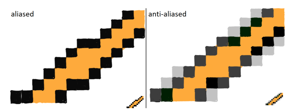
Normally, GPUs perform the coverage test checking the geometry coverage at the very center of the pixel. If the edge of the geometry comes really close to the pixel center, but it doesn’t touch it, the pixel will not be lit at all. This is showed on the left part of the figure 7.
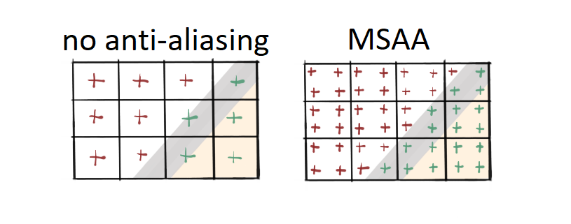
One of the techniques to prevent geometrical aliasing is called Multi-Sampling Anti-Aliasing, or MSAA for short. The bottom-line of this technique is this – instead of testing coverage at the center of the pixel, you test it in some defined number of points, so kind of testing on a sub-pixel level. If you talk about 4x MSAA, you test at four sub-pixel locations, and so on. This is showed on the right side of figure 7. MSAA yields better results but it is significantly slower.
The values at DXGI_SAMPLE_DESC structure relate to MSAA. The Count member contains the number of sub-pixel tests to preform. The Quality member lets you pick a sweet spot between the performance and the output quality of the effect.
Now here comes the big one – this is how it worked in DirectX 11. In DirectX 12 you can no longer create MSAA like that, you have to implement it manually, on your own. So whenever you set the Count member to more than one in DX12, you won’t be able to create a Swap Chain.
Disabling Fullscreen Transition
If you would run our program at this point and press Alt + Enter you would notice something interesting. It turns out that by default DXGI monitors your Message Queue and whenever it detects the Alt + Enter shortcut, it starts the procedure of maximizing the window. The procedure puts some messages on the Queue, like WM_STYLECHANGING, WM_WINDOWPOSCHANGING or WM_NCCALCSIZE that leads to the situation where your window’s client area covers the entire screen.
The problem is, it only applies to the window’s client area, not the surfaces that we use in the Swap Chain. That can lead to a wierd looking output, as shown on figure 8.

In order to properly handle this, we need to be able to forbid DXGI from monitoring our message queue and handle the procedure ourselves, including changing the render target size as well. We will cover that later in the future. For now, let’s simply disable this functionality.
void Renderer::DisableDxgiMsgQueueMonitoring() {ExitIfFailed(dxgiFactory->MakeWindowAssociation(hwnd,DXGI_MWA_NO_WINDOW_CHANGES));}
The MakeWindowAssociation() function comes to the rescue. The first parameter indicates which window message queue is affected, and the DXGI_MWA_NO_WINDOW_CHANGES prevents DXGI from monitoring the queue, which makes DXGI unable to respond to mode changes and Alt+Enter.
There is also another option there, the DXGI_MWA_NO_ALT_ENTER. I tried to find the differences between the two, but I couldn’t. In theory, the first one is more generic and forbids DXGI to monitor messages related to Alt+Enter and any window mode changes, while the second only applies to Alt+Enter. Just to be on the safe side, we picked the first one. Don’t forget to call the function after the CreateSwapChain function call in the Renderer constructor.
Report Live Objects
We will implement one more feature that is not strictly related to the Swap Chain. This feature will report any living COM objects when the application closes. Hopefully, there will be none. It will simply tell you if you forget to release any COM objects.
Engine::~Engine()
{
  if (renderer)
  {
    delete renderer;
  }
#if _DEBUG
  ReportLiveObjects();
#endif
}
We will implement the new function ReportLiveObjects that will do just that. It will be best to put it in the Engine class destructor, since this is one of the latest destructor to be called. By that time there should be no more COM objects. As for the function itself, this is how it looks like.
void Engine::ReportLiveObjects()
{
  IDXGIDebug* dxgiDebugInterface;
  if (SUCCEEDED(DXGIGetDebugInterface1(0,
    IID_PPV_ARGS(&dxgiDebugInterface))))
  {
    dxgiDebugInterface->ReportLiveObjects(DXGI_DEBUG_ALL,
      DXGI_DEBUG_RLO_FLAGS(DXGI_DEBUG_RLO_SUMMARY |
      DXGI_DEBUG_RLO_IGNORE_INTERNAL));
  }
  SafeRelease(&dxgiDebugInterface);
}
In order to use our function, we need to obtain the IDXGIDebug interface. We can do that by calling the function DXGIGetDebugInterface1(). Then, on that interface, we can call the ReportLiveObjects() function, which takes two arguments. First are the GUIDs of the interfaces we want to monitor. Fortunately, there are useful constants we can use – the DXGI_DEBUG_ALL covers all Direct3D and DXGI objects, which is the most useful for us. The second argument specifies the amount of information to report. We’ve picked RLO_SUMMARY and RLO_IGNORE_INTERNAL to report information about objects lifetime and to ignore internal objects, so we can focus only on our objects.
If we forget to release any of the objects we used, we should get a message like the one below. Note that I edited the message a little bit to fit the screen.
10:36:41 - Sapphire::Engine::~Engine()
10:36:41 - Sapphire::Renderer::~Renderer()
D3D12 WARNING: Live ID3D12Device at 0x00, Refcount: 8
D3D12 WARNING: Live ID3D12CommandQueue : 1
D3D12 WARNING: Live IDXGISwapChain : 1
D3D12 WARNING: Live ID3D12LifetimeTracker : 1
D3D12 WARNING: Live ID3D12Fence : 2
D3D12 WARNING: Live ID3D12CommandAllocator : 1
D3D12 WARNING: Live ID3D12GraphicsCommandList :
This should give us enough information to know where to look for unreleased objects and properly release them.
Performance Corner
In this episode of the Performance Corner we will take a look at the very useful tool that is right under our nose. I mean, if you are using Visual Studio 2019. I’m talking about about the Performance Profiler.
In order to run a performance profiling session, first you need to open the tool. You can do that by clicking Debug > Performance Profiler, or you can just push Alt+F2 shortcut.
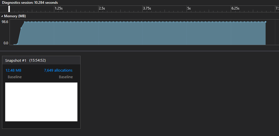
The way it works is that we take snapshots of the memory heap, as shown on the figure 9. Then, we can pick any of the snapshots and see some more details about that moment in the program.
| Your details window might look a little different than mine. One of the reasons for that might be that there are no symbols attached. The symbols allow Visual Studio to resolve function names from function addresses. To enable symbols go to Tools > Options and then select Debugging > Symbols. In the “Symbol file (.pdb) Symbol Servers” select “Microsoft Symbol Servers”. Be patient, it might take a little while to download them. |
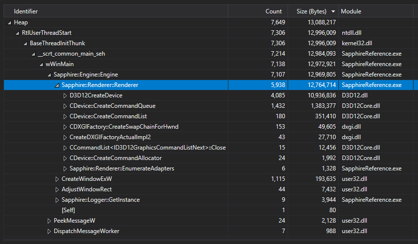
On figure 10 we can see more details about the heap memory allocations on chosen snapshot. So the Count represents roughly the amount of heap allocations and the Size in bytes represents total amount of memory allocated up to this point, so the sum of all entities below given line.
Starting on top, we can see that our application made about 7.6K allocations and allocated 13MB in total of heap memory. When we unroll the tree, we can see that most of that memory was allocated in the Engine constructor, specifically when we create a new Renderer. Remember, the Renderer is so far our only class allocated on the heap, the rest is on the stack.
In the Renderer constructor, the biggest allocators were D3D12CreateDevice (10MB from D3D12.dll), followed by 1.5MB allocated by the CDevice::CreateCommandQueue from D3D12Core.dll module. Also, at the bottom there is a line that says “[Self]” – it represents the allocations for the Renderer class itself. We only created one instance and it took about 80 bytes. We store all of our Renderer class members in there.
Summary
In this chapter there was a little bit more theory than practice, but it is ok – there is a lot of practice ahead of us. The Swap Chain and the way it works is crucial to have a solid understanding of the game engines. We discussed screen tearing and how Swap Chain can help us prevent this undesired effect. We’ve discussed all the necessary settings to create Swap Chain and in the end we’ve created it. Now we have two buffers, the Front Buffer and the Back Buffer, that we will use to render and present the frame, minimizing the screen tearing effect. We’ve disabled the transition to fullscreen for now. We’ve also learned a little about the DWM and its role in frame presentation. Finally, we’ve added a new debug functionality – if we ever forget to release COM object, we should now see it listed.
The window hasn’t changed with the new implementation, however, we know that behind the courtains we have built a foundation for frame presentation.
In the next chapter we will create a frame presentation framework, which is like a pulse for the game engine. We will make our game loop present our Back Buffer every iteration. We will take care of the synchronization to make sure that we are presenting content in the unchanged state and we will synchronize the presentation pace to the display VSync signal.
Source code for this part of the course can be found under chapter “CH05” in this repository here: https://github.com/bboczula/GameEngineCourse.git