Introduction
I think this is the high time to get to know the GPU a little better, since it will be doing a lot of work for us in the near future. In this chapter we will have a closer look at the GPU pipeline. We will learn a little bit about why it is called a pipeline as well as we will learn just a little bit about the functionality of each pipeline stage.
Based on that knowledge, we will create a so-called Pipeline State object and a Root Signature that are associate with it. We will also use the shaders that we created in the previous chapter to bind them to the Pipeline State object as well.
Architecture
In this chapter we have a really clean architecture update. We will create only one new class and we will simply plug it into the existing architecture.
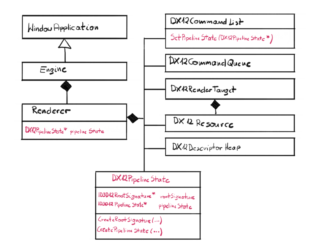
This new class is DX12PipelineState and will encapsulate the behavior of creating and binding the Pipeline State objects. It is also a wrapper of two pointers, the ID3D12RootSignatrue and ID3D12PipelineState, which is in line with the policy, where we want to create a layer that will wrap all DirectX pointers, so the higher layer won’t be messing up with it.
A pointer to the newly created class will be added to the Renderer, and a new method SetPipelineState() will be added to the Command List class.
GPU
In order to proceed further, we need to pause for a second and spend some time to understand the nature of the GPU. I can’t stress enough how important this section is. I remember when I was first learning how to develop DirectX programs, I kind of skimmed through this section, so I could get to the code as soon as possible. And even though it wasn’t a mistake per-se, I would have saved myself a significant amount of time if you learn this from the start instead of coming back later.
From the high level point of view, GPUs are very much like your PC. Similar to the CPU, they have cores that can execute programs. Dedicated GPUs also have dedicated memory, similar to what RAM is to the CPU. But even though they might look very similar, their spirit is very much different. To put it simply – CPUs are all about executing single thread as fast as possible and GPUs are all about executing as many very simple threads as possible. Below you can find a simple comparison of some of the characteristics of both CPU and GPU. For the CPU I have picked Intel i9-10900K and for the GPU I have picked NVidia RTX2080.
| CPU | GPU | |
| Number of cores | 10 | 3000 |
| Single core clock | 5.0 GHz | 1.7 GHz |
| Memory type | DDR4 (3200 MHz) | DDR6 |
| Memory size | 32 | 8 |
| Memory throughput | 25 GB/s | 450 GB/s |
| Instruction Set | Complex | Simple |
| Preferred processing | Serial | Parallel |
If you look at the table x it should become clear what is the difference between CPU and GPU. GPUs tend to have an order of magnitude when it comes to number of cores. Those cores however are clocked significantly lower, which makes them generally slower. CPUs generally have less, but way more powerful cores.
Another big difference is in between local memory. CPUs generally have way more RAM available for processing, but it is usually an older technology and lower throughput. GPUs on the other hand, are all about the throughput, not the amount of memory. You can easily find dedicated GPUs with 3 GB of VRAM which for CPU is almost impossible to run anything with this amount.
Finally, the instruction set. CPUs can be programmed in many languages, but even on the assembly level you can see that they have a lot of available instructions and sometimes they can be very complex. That is because CPU architecture is generally pretty complex and allow for that design. GPUs on the other hand have rather simple architecture, and because of that the instruction set is very limited and available instructions are rather simple.
The bottom line from this argument is this – CPUs are generally designed to process a single, complex task as fast as possible, while GPUs are designed to process a lot of data in parallel, running a very simple program on a slow and simplified cores on the subset of the input data set. This is also referred to as SIMD – single instruction multiple data. For instance, GPUs are great at processing thousands of pixels in parallel, where for each pixel the same program is being run to calculate its color.
GPU Pipeline
Since GPUs have very specific purpose – to turn a bunch of geometry stored in a mathematical form into a flat image on the screen – their execution model is very well defined. There are several specific stage of execution, and the collection of those stages are referred to as the pipeline.
The pipeline defines the order and function of stages. The simplified model GPU pipeline can be examined on the figure 2. Each stage processes the data output from the previous stage, and passes the data down to the next stage.
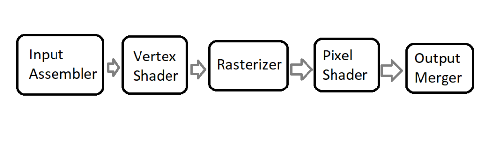
Most stages are programmable, in a way that it has some settings that you can change. Some of the stages, like Vertex Shader and Pixel Shader can even have programs attached to. Those programs are written in HLSL and are compiled to bytecode by the GPU driver. HLSL is a very simple language with a syntax similar to C++, however its complexity level is nothing next to C++. HLSL doesn’t have any of the advanced structures, like pointers, references or classes, nothing like that. It has some instructors and types specific to the graphics programming though.
Input Assembler
This is the first stage in the pipeline. It’s main purpose is to collect the input geometry data that the user provides in form of various buffers, and assemble that data into primitives, that will be then used later down the pipeline.
We are doing this mainly by defining the layout of the input vertices, meaning describing each member and how it maps to the types recognizable by the vertex shader. This definition is also known as Input Layout.
Vertex Shader
The second stage of the GPU pipeline deals with the geometry. We already know the Input Layout and now is the time to process those vertices.
Vertex Shader is a GPU program that will be run for every vertex on the input. So if you have a single triangle, that means that three instances of the same Vertex Shader code will be spawned, and each will process a different vertex.
Rasterizer
Rasterizer is a stage where the magic happens. This is where the geometry mathematically visible from the camera perspective, gets “translated” into pixels on the screen. For every input triangle, Rasterizer performs a coverage test to see which pixels are covered by it. If the pixel is covered, a single instance of the Pixel Shader is spawned. Rasterizer is also a stage where the interpolation happens.
Interpolation – generally speaking – is guessing some value based on the neighboring values. For example if you provide a color for each vertex, each Pixel Shader will get the interpolated color value based on the distance from those defined colors. This is a little bit more complicated than this, and we will cover that later in the future.
Pixel Shader
Similar to Vertex Shader, Pixel Shader is also a GPU program, but this one is called for every pixel covered by the geometry. Those are not yet pixels, and that is the reason why some people refer to those as fragments. The main purpose of the Pixel Shader is to calculate the color of that pixel.
Output Merger
Final stage of the pipeline is Output Merger. This class takes pixel that are about to be written to the Render Target and performs a blending operation on them. This allows for some interesting effects, like for example semi-transparent surfaces.
Pipeline State Object
As a GPU programmer, you can not only write shaders to be executed on the GPU, but you can also control a good amount of stages in the GPU pipeline. A set of such defined properties are called the GPU Pipeline State. In DirectX 12 there is an interface that abstracts this pipeline state. Generally there are various structures, each controlling the corresponding GPU stage. On top of that, a part of the Pipeline State are also the compiled shaders. Then in during recording of the Command List, we can set the entire pipeline state with a single command.
Class Design
Let’s take a look at the interface of the DX12PipelineState class.
class DX12PipelineState
{
  friend class DX12CommandList;
public:
  DX12PipelineState(DX12Device* device,
    DX12Shader* vertexShader, DX12Shader* pixelShader);
  ~DX12PipelineState();
private:
  void CreateRootSignature(DX12Device* device);
  void CreatePipelineState(DX12Device* device,
    D3D12_SHADER_BYTECODE vs, D3D12_SHADER_BYTECODE ps);
  ID3D12RootSignature* rootSignature;
  ID3D12PipelineState* pipelineState;
};
The input parameters would be pointers to the Device and compiled Vertex and Pixel Shaders. That would mean that for the time being, we will only be able to have one Pipeline State, but we would have possibilities to use different shaders. We will have to address this problem in the future, because we would very much like to be able to have possibility to have many Pipeline States, but we will cross that bridge when we get there.
The DX12PipelineState class will wraps some functionality around two raw COM pointers: ID3D12PipelineState and ID3D12RootSignature. The Root Signature is a big topic, so it will have to be covered in more detailed in the future. In this chapter we will only introduce the concept.
Constructor
The constructor, as usual, is pretty simple and self explanatory.
DX12PipelineState::DX12PipelineState(DX12Device* device,
  DX12Shader* vertexShader, DX12Shader* pixelShader)
{
  CreateRootSignature(device);
  CreatePipelineState(device,
    vertexShader->GetBytecode(), pixelShader->GetBytecode());
}
We simply have to create a Root Signature first, and then we have to create the actual Pipeline State.
Root Signature Creation
Now let’s make something clear – Root Signatures are very important subject when learning DirectX 12. A Root Signature – even empty – is required to create Pipeline State. So for now, we will just provide a general definition of Root Signature and we will create an empty one, and we will return to this subject later.
Up to this point we are aware that DirectX 12 resources exist. Resources are not only textures (which we were given to us during the Swap Chain creation), but – which we will learn very soon – also the general data used in the shaders. We also know that resources can have different ways to interpret them (a.k.a. the “views”). Finally, we are aware that Descriptors store the information about the vies, and Descriptors are stored at the Descriptor Heaps.
The Root Signature is actually a link between all the available resources and resources that particular shaders use. In other words, Root Signatures allow us to use only subset of all available resources, that the shaders actually use. Root Signatures also determines the types of data the shaders should expect, but does not define the actual memory occupied by that data. In that way, it is similar to the function signature in C++, but for the entire GPU pipeline.
void DX12PipelineState::CreateRootSignature(
  DX12Device* device)
{
  CD3DX12_ROOT_SIGNATURE_DESC rootSignatureDesc;
  rootSignatureDesc.Init(0, nullptr, 0, nullptr,
    D3D12_ROOT_SIGNATURE_FLAG_ALLOW_INPUT_ASSEMBLER_INPUT_LAYOUT);

  ID3DBlob* signature;
  ID3DBlob* error;
  ExitIfFailed(D3D12SerializeRootSignature(&rootSignatureDesc,
    D3D_ROOT_SIGNATURE_VERSION_1, &signature, &error));
  ExitIfFailed(device->GetDevice()->CreateRootSignature(0,
    signature->GetBufferPointer(), signature->GetBufferSize(),
    IID_PPV_ARGS(&rootSignature)));
}
This function creates an empty Root Signature, since our shaders are not using any external data. To create that, we are using the CD3DX12_ROOT_SIGNATURE_DESC structure, and the very useful Init() function that comes with it. With the input parameters, we simply state that there are no data in the Root Signature. Let’s leave this like that for a moment. Let’s also leave the serialization of the Root Signature until we will cover this in details.
Pipeline State Creation
The last phase is the actual Pipeline State creation.
void DX12PipelineState::CreatePipelineState(DX12Device* device,
  D3D12_SHADER_BYTECODE vs, D3D12_SHADER_BYTECODE ps)
{
  D3D12_INPUT_ELEMENT_DESC inputElementDescs[] =
  {
    { "POSITION", 0, DXGI_FORMAT_R32G32B32_FLOAT, 0, 0,
      D3D12_INPUT_CLASSIFICATION_PER_VERTEX_DATA, 0 }
  };

  D3D12_GRAPHICS_PIPELINE_STATE_DESC psoDesc;
  ZeroMemory(&psoDesc, sizeof(D3D12_GRAPHICS_PIPELINE_STATE_DESC));
  psoDesc.InputLayout = { inputElementDescs,
    _countof(inputElementDescs) };
  psoDesc.pRootSignature = rootSignature;
  psoDesc.VS = vs;
  psoDesc.PS = ps;
  psoDesc.RasterizerState = CD3DX12_RASTERIZER_DESC(D3D12_DEFAULT);
  psoDesc.BlendState = CD3DX12_BLEND_DESC(D3D12_DEFAULT);
  psoDesc.DepthStencilState = CD3DX12_DEPTH_STENCIL_DESC(
    D3D12_DEFAULT);
  psoDesc.SampleMask = UINT_MAX;
  psoDesc.PrimitiveTopologyType =
    D3D12_PRIMITIVE_TOPOLOGY_TYPE_TRIANGLE;
  psoDesc.NumRenderTargets = 1;
  psoDesc.RTVFormats[0] = DXGI_FORMAT_R8G8B8A8_UNORM;
  psoDesc.SampleDesc.Count = 1;

  ExitIfFailed(device->GetDevice()->CreateGraphicsPipelineState(
  &psoDesc, IID_PPV_ARGS(&pipelineState)));
}
This is the function where we will create our first Pipeline State object. For the time being, we will pick the simplest possible solution that would allow us to move forward. That means that all of the states are going to be hardcoded. That basically means that we will only be able to support one Pipeline State object. On top of that, we will only be able to support one set of Vertex Shader input parameters. For now this will suffice, but in the future – where we will definitely want to support more states and where we will definitely will not want to be bound with a specific shader input – we will address all of those issues.
Input Layout
The very first things that we have to do is we have to define the layout of the input data that enters the Input Assembler and eventually the Vertex Shader. This is a link between the input data structure that we are using in the Vertex Shader and the data that we will feed from the CPU side.
In the Input Layout, each element in the array describes one field in the input structure. Let’s get a quick look on how we defined the input data in the Vertex Shader source code.
float4 main( float4 pos : POSITION ) : SV_POSITION
{
	return pos;
}
The input data structure is very simple – it has only one field pos, of the semantics POSITION and it is of the type of float4, which basically means a vector of four float values. So now it is obvious that in our Input Layout array we will only have one element. Let’s have a closer look at that element.
D3D12_INPUT_ELEMENT_DESC inputElementDescs[] =
{
  { "POSITION", 0, DXGI_FORMAT_R32G32B32_FLOAT, 0, 0,
    D3D12_INPUT_CLASSIFICATION_PER_VERTEX_DATA, 0 }
};
The first three elements of D3D12_INPUT_ELEMENT_DESC are as follows. The first one is the semantics, so this have to match what we have in HLSL code, which is “POSITION”. Second parameter is the samantic index. Some of the semantics can have indices, like TEXCOOD1, TEXCOOD2 and so on. We only have one POSITION semantic, so we will eave it at zero. Next is the format. We basically need four floats, so the closest DXGI format would be DXGI_FORMAT_R32G32B32_FLOAT.
Then there are a bunch of not important parameters, except for the input class. We set this value to D3D12_INPUT_CLASSIFICATION_PER_VERTEX_DATA. We had other option of PER_INSTANCE data. This will become useful in the future, where we will add a feature of instanced rendering, but for now we will stick with the per-vertex input data. Input classification defines the type of data contained in an input slot, weather it is per-vertex or per-instance of the geometry.
D3DX12 Helper Library
Next we have to setup the rest of the Pipeline State. You might notice however that some strange new types appeared. I’m talking about CD3DX12_DEPTH_STENCIL_DESC type. This is not native DirectX type, but rather a very useful wrapper so we don’t have to care about too many parameters if we don’t really need them, so we can just focus on the important ones.
All of the goodies come in a format of a single header library called D3DX12 and you can find it here. Since this is just a single header, I just copied that file over and added it to the solution. Thanks to that, I have easy access to everything I want and maybe in the future I would want to expand it. Be careful though, some of the structures in that library might be correlated with a different SDK then the one you have locally, so there can be some compilation errors to deal with.
Now as mentioned before, this library contains helpful wrapper functions over some native DirectX structures. The wrappers basically simplify usage of those structure, making you type little less and at the same time making the code a little bit cleaner.
Let’s take a look at the structure D3D12_RASTERIZER_DESC containing information about the Rasterizer in the Pipeline State object. Without the helper library you would have to initialize this structure all by yourself. At this point that would basically mean that you will have to stop, read the documentation about every member and then try to figure out what value to put in there. On top of that, you would end up with additional dozen lines of code. Let’s see how the helper library wraps that structure up.
struct CD3DX12_RASTERIZER_DESC : public D3D12_RASTERIZER_DESC
{
  CD3DX12_RASTERIZER_DESC() = default;
  explicit CD3DX12_RASTERIZER_DESC(const D3D12_RASTERIZER_DESC& o)
    noexcept : D3D12_RASTERIZER_DESC(o)
    {}
  explicit CD3DX12_RASTERIZER_DESC(CD3DX12_DEFAULT) noexcept
  {
    FillMode = D3D12_FILL_MODE_SOLID;
    CullMode = D3D12_CULL_MODE_BACK;
    FrontCounterClockwise = FALSE;
    DepthBias = D3D12_DEFAULT_DEPTH_BIAS;
    DepthBiasClamp = D3D12_DEFAULT_DEPTH_BIAS_CLAMP;
    SlopeScaledDepthBias = D3D12_DEFAULT_SLOPE_SCALED_DEPTH_BIAS;
    DepthClipEnable = TRUE;
    MultisampleEnable = FALSE;
    AntialiasedLineEnable = FALSE;
    ForcedSampleCount = 0;
    ConservativeRaster = D3D12_CONSERVATIVE_RASTERIZATION_MODE_OFF;
  }
  explicit CD3DX12_RASTERIZER_DESC(
    D3D12_FILL_MODE fillMode,
    D3D12_CULL_MODE cullMode,
    BOOL frontCounterClockwise,
    INT depthBias,
    FLOAT depthBiasClamp,
    FLOAT slopeScaledDepthBias,
    BOOL depthClipEnable,
    BOOL multisampleEnable,
    BOOL antialiasedLineEnable,
    UINT forcedSampleCount,
    D3D12_CONSERVATIVE_RASTERIZATION_MODE conservativeRaster)
      noexcept
  {
    FillMode = fillMode;
    CullMode = cullMode;
    FrontCounterClockwise = frontCounterClockwise;
    DepthBias = depthBias;
    DepthBiasClamp = depthBiasClamp;
    SlopeScaledDepthBias = slopeScaledDepthBias;
    DepthClipEnable = depthClipEnable;
    MultisampleEnable = multisampleEnable;
    AntialiasedLineEnable = antialiasedLineEnable;
    ForcedSampleCount = forcedSampleCount;
    ConservativeRaster = conservativeRaster;
  }
};
First and foremost, the CD3DX12_RASTERIZER_DESC class derives from D3D12_RASTERIZER_DESC. That automatically allows us to use this structure wherever the base type is required, like in the native Pipeline State object instance.
| The explicit keyword in front of the constructor forbids and implicit conversion of the input parameter. |
Second, note that this class doesn’t contain anything else than a bunch of constructors. In this case, we have four of them. First is the default one and the second is the one that creates new CD3DX12 kind of structure using the native type. The last constructor basically takes every member of the structure as input parameter. The third constructor is actually the one that is the most useful for us. It takes the CD3DX12_DEFAULT structure which is in fact an empty structure and it is an explicit way of showing the intent. What it does for us is basically setting every member of the base structure to the default value. Thanks to this, we don’t have to pay too much attention to what to put where, which at this point is not really important.
DX12CommandList Update
The last thing that we have to cover in this chapter is update to the Command List class. As you remember, we want to pack functionalities into functions – we don’t want the end user to explicitly call the functions on raw Command List pointer. Since now we should have the Pipeline State object ready, we have to add the function SetPipelineState that takes that DX12PipelineState pointer as an argument. This function is really simple.
void DX12CommandList::SetPipelineState(
  DX12PipelineState* pipelineState)
{
  commandList->SetGraphicsRootSignature(
    pipelineState->rootSignature);
  commandList->SetPipelineState(pipelineState->pipelineState);
}
Since DX12CommandList class is a friend of DX12PipelineState class, we have access to the private member of the latter. This gives us all the data that we need, which is a pointer to raw Root Signature instance and a pointer to raw Pipeline State instance. We just have to call the functions in that correct order and we are done.
Performance Corner
Now it would be a good time to have a look at what RenderDoc has to offer, since we are setting some states at the GPU. Let’s capture a frame and see what information we can find.
The information about the GPU state can be found in the Pipeline State tab. There are a bunch of rectagles where each represents a state in the simplified GPU pipeline, as we can see in the figure 3. If the rectangle is grayed out it means that it was not used during captured frame. We can click on each rectangle to find more information about the stage.
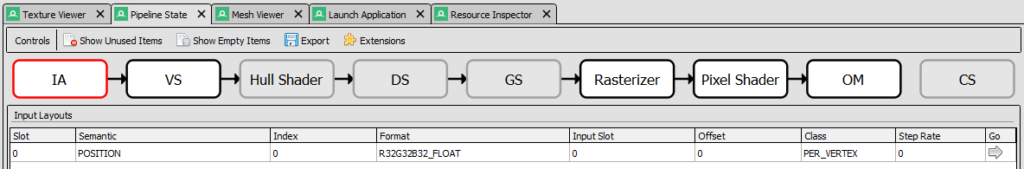
In the Input Assembler (IA) stage we can find detailed information about Input Layout. In that section we can also find details about input geometry data.
In the Pixel and Vertex Shader sections (VS and PS) we can find information about used shaders. We can also view the compiled code. Sometimes RenderDoc can also create the HLSL version from the complied code and would let us change the actual HLSL code to alternate the output.
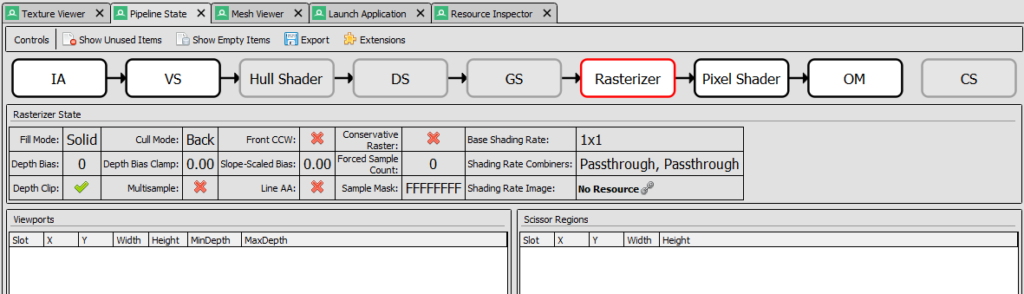
In the Rasterizer section, there is this table where we can quickly see the value of the most important input parameters. In the figure 4 we can see that only Depth Clip was enabled (we used the default values from the helper library). There are also information about associated Viewports and Scissors, which we will cover in the next chapter.
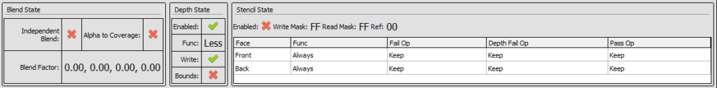
Finally in the Output Merger section there are information about bound Render Targets and blending modes. At the bottom of the screen there is also a useful table that displays all input values of the OM state.
It should become clear now that RenderDoc is very useful tool in GPU programming and that is the reason why we are learning how to use it from the very beginning.
Summary
That was quite some information right there. Don’t worry, this is all really important. Additionally, this is only an introduction. To be aligned with the spirit of the course, I only introduced what is necessary to get something functionally working. We left the details about some of the states out, thanks to a useful D3DX12 helper library.
We have introduced the concept of a Root Signature. We now know that this is very similar to a function signature in the C++ and is a connection between the shader parameters and the actual data that will be passed to them. Finally, we have created one empty Root Signature to be bound with the Pipeline State since it is required.
We have now a basic knowledge about GPU pipeline. We can name some of the most important stages of the pipeline and we can list its most general responsibilities. On top of that knowledge, we have introduced the Pipeline State object and its parameters. Finally, we have associated our shaders from the last chapter, as well as some default states in our Pipeline State object and we have successfully (as seen in the RenderDoc) set the desired GPU pipeline set.
There are no visual changes in this chapter, except the one that the screen is no longer blinking, but now we have all the ducks in a row. In the last chapter – which is also be the final chapter of the first part of the course – we will display the first triangle on the screen. This might not be much, but trust me – there is not that much distance between displaying a single triangle and displaying a thousands triangles that represents some game object.
Source code for this part of the course can be found under chapter “CH09” in this repository here: https://github.com/bboczula/GameEngineCourse.git